
 Custom Design. Factory Made. Globally Delivered CREAX


The Complete Guide to Mirror Switch Modules: Technology, Selection, and Installation
A mirror switch module controls lighting, dimming, and defogging in smart bathroom mirrors. This guide covers capacitive, infrared, and mechanical types, key electrical specifications, installation steps, selection criteria, and quality-testing practices for reliable LED mirror applications.
The Complete Guide to Mirror Switch Modules: Technology, Selection, and Installation
Understanding the Mirror Switch Module and Its Core Functions
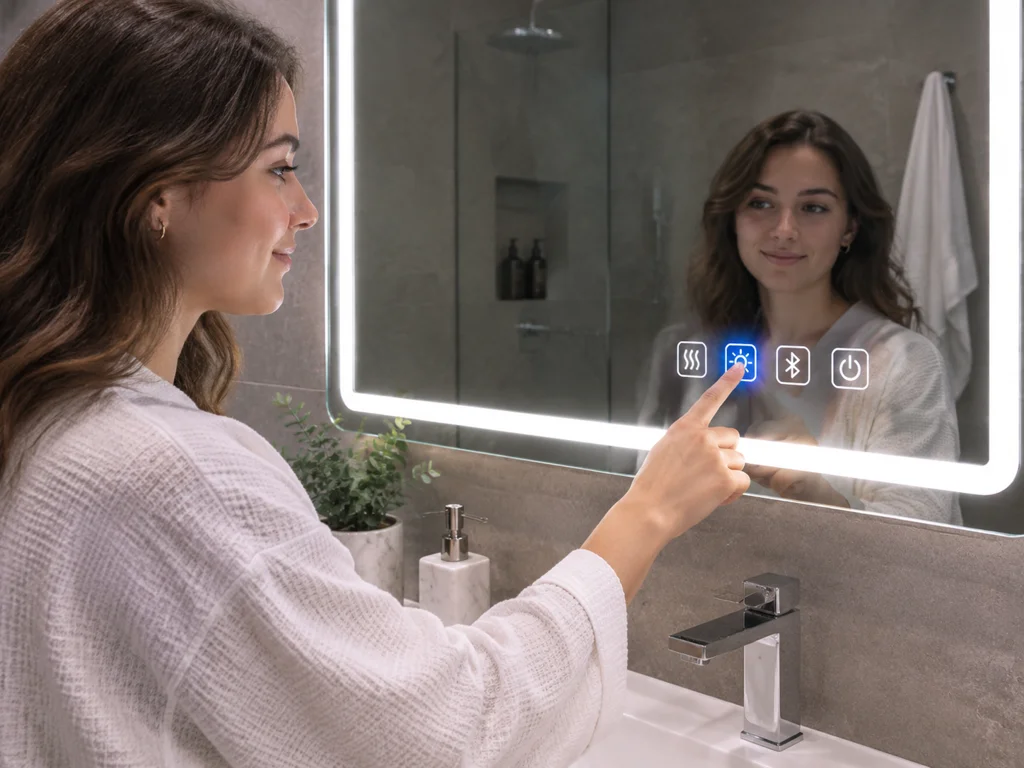
A mirror switch module is the central control unit embedded in a smart vanity mirror or bathroom mirror that manages lighting, defogging, and auxiliary features. In its most basic form, the module turns the integrated LED strip on and off; in more advanced configurations, it enables dimming, color-temperature switching, touch-activated defogger control, and even ambient lighting presets. For manufacturers, interior designers, and overseas buyers sourcing bathroom mirrors, the mirror switch module determines not only the user experience but also the electrical safety and long-term reliability of the entire product.
Modern bathroom mirror switch modules are designed to work with a wide range of mirror configurations, from slender backlit mirrors to large cabinet mirrors with inset LED strips. A typical unit consists of a sensing panel, a microcontroller board, a power regulator, and an output stage that drives the LED lighting and heating pad. The sensing panel is usually made of tempered glass with a conductive coating, while the control board is housed in a sealed plastic enclosure to resist humidity and condensation. Because the mirror surface itself is the user-interface layer, the module must be sensitive enough to register touches through the mirror coating yet robust enough to ignore water splashes and cleaning agents.
From an engineering perspective, the mirror switch module is the intersection of low-voltage power distribution, human-machine interaction, and thermal management. When you press a capacitive touch area on the mirror surface, the module detects the change in capacitance, debounces the signal, and commands the LED driver to change state or intensity. This simple interaction, repeated tens of thousands of times over the life of the mirror, is why the quality of the switch module directly impacts customer satisfaction. In our experience with contract manufacturing for European and North American bath brands, most field returns for \\\\\\\"faulty mirror\\\\\\\" are actually caused by an under-specified switch module, not by the mirror glass or the LED strip itself.
There are three broad categories available on the market today: mirror light switch modules that only control the front light, led mirror switch modules that manage both front and back lighting with dimming, and full-function bathroom mirror switch modules that integrate defogger, temperature display, and even Bluetooth speakers. The price difference between these tiers is significant, but so is the internal component quality. Understanding these categories is the first step toward making an informed sourcing decision.
Technology Types: Capacitive, Infrared, and Mechanical Modules
Choosing the right sensing technology is the single most consequential decision when specifying a mirror switch module. The three common types are capacitive touch, infrared proximity, and mechanical push-button. Each has distinct advantages in terms of durability, response, water resistance, and manufacturing cost.
Capacitive touch modules dominate the premium segment. They work by measuring the change in capacitance when a finger comes into contact with or close to the glass surface. Since there is no opening in the mirror, capacitive modules achieve the highest water-resistance ratings and are the preferred choice for bathrooms with direct shower exposure. They also support smooth gestures such as sliding a finger along the mirror edge to dim the light. However, they require careful tuning during production to reject interference from the LED driver and from moisture films on the mirror surface.
Infrared modules use a small IR emitter and receiver pair behind a tiny slot or glass window. They are triggered when a finger interrupts the beam, which works even with thick glass and does not require direct contact. The downside is that a visible or semi-visible window must be created in the mirror coating, and the sensor opening can accumulate dust or fog over time. Infrared modules are common in mid-range mirrors because they are easier to integrate with large glass panels and are less sensitive to capacitive grounding issues.
Mechanical push-button modules are the oldest type, using a micro switch behind a rubber or silicone pad recessed in the mirror frame. They provide a tactile click, which some users still prefer, and they are very easy to service. They are also the least expensive to source. The main drawbacks are the reduced aesthetic value, the physical opening that allows humidity ingress, and a shorter mechanical lifespan.
| Feature | Capacitive Touch | Infrared Proximity | Mechanical Push-button |
|---|---|---|---|
| Response method | Direct contact or near-touch | Non-contact beam interruption | Physical press |
| Typical operational lifetime | >1,000,000 touches | >500,000 activations | ~50,000 presses |
| Water and dust resistance | Excellent (sealed behind glass) | Good (small opening must be sealed) | Fair (crevice ingress risk) |
| Aesthetic integration | Fully flush, invisible sensor | Small visible window or cutout | Visible button on frame or surface |
| Component cost | Highest | Moderate | Lowest |
For a bathroom mirror switch module intended for export to humid coastal regions or hotel applications, we strongly recommend a capacitive design with an IP65-rated control board. In an accelerated test we conducted over a 600-hour salt-spray cycle, capacitive modules with conformal-coated printed circuit boards maintained full touch response, whereas mechanical modules in the same enclosure failed due to contact corrosion.
Critical Electrical and Safety Specifications
Beyond the sensing method, the electrical characteristics of a mirror switch module determine whether a mirror product passes safety certification and operates reliably for years. A professional-grade led mirror switch module should be rated for the full input range of 100–240 V AC if it includes an integrated power supply, or 12/24 V DC if it is used with an external LED driver. Most modern mirrors use a low-voltage LED strip, which places the switch module on the secondary side of the power chain; this arrangement reduces shock risk and simplifies regulation compliance.
One of the most overlooked parameters is the number and type of output channels. A basic mirror light switch module has a single channel, while a premium module offers two or three channels: one for the main front light, one for the backlight or ambient glow, and one for the defogger pad or fan. Each channel should be independently rated, commonly 2 A per channel at 24 VDC, which is sufficient for a 48 W LED load. If the mirror is expected to drive a heated demister pad that draws 1.5 A, the module must not only supply that current but also handle the inrush surge when the heating element is cold.
Protection features are equally critical. Look for an overcurrent trip, an over-temperature shutoff, and reverse-polarity protection on the DC input side. These safety circuits prevent catastrophic failures in the event of mis-wiring, which is a common occurrence on construction sites. We also recommend modules that comply with IEC 60335-1 and, for the EU market, the Low Voltage Directive and EMC Directive 2014/30/EU. Without these certifications, an LED mirror fitted with an uncertified switch module will face detention or rejection at customs in many countries.
Another practical specification is the standby power consumption. A bathroom mirror switch module that remains in low-power listening mode for touch detection should draw less than 0.3 W. This matters for energy-rating labels and for battery-backed mirrors installed without a nearby socket. In our own product qualification, we measure standby current over a 72-hour window to ensure that the microcontroller, the sensing electrodes, and the status LED together do not exceed the data-sheet limit. A poorly designed module can quietly consume 2–3 W in standby, causing visible heat buildup behind the glass and a shortened service life.
Step-by-Step Installation and Wiring Guide
Installing a mirror switch module is a straightforward process for a qualified electrician or factory assembly technician, but common wiring mistakes lead to premature failure. The following procedure assumes a backlit mirror with a separate low-voltage LED driver and a capacitive sensing module mounted on the back surface of the glass.
Preparation and safety. Disconnect all power sources. Lay the mirror face-down on a clean and cushioned bench. Identify the pre-drilled access holes or the mounting brackets for the module. Wearing grounded anti-static gloves, remove the module from its anti-static bag and inspect the connector pins for any signs of damage.
- Mount the module with its plastic support frame aligned to the sensing electrode marks printed on the mirror coating. The frame must be pressed evenly so that the adhesive layer makes full contact; a gap as small as 0.2 mm reduces touch sensitivity.
- Connect the low-voltage input cable from the power supply to the module’s input terminals. Observe polarity: the module is typically marked V+ and V–. Use a crimp connector or solder joint, then cover the joint with heat-shrink tubing.
- Connect the LED light harness to the output terminals labeled LED1 (front light) and LED2 (backlight if available). If the module has a defogger output, connect the heating pad across that terminal set. Do not exceed the rated current printed on the module housing.
- For a defogger controlled by an external timer, connect the optional enable wire to the input terminal of the heating element. The default timer in most modules is 30 minutes, which can be adjusted via a small trim potentiometer on the board.
- Reapply power and test the module BEFORE sealing the back panel. Confirm that each touch command cycles the light as expected, that dimming is smooth, and that the defogger activates within five seconds and shuts off after the set time.
- Apply a bead of neutral silicone sealant around the module housing to create an additional moisture barrier, then close the mirror back panel.
A word of caution: never install the module directly behind a mirrored area that is exposed to continuous water spray from a shower head. Even with an IP65 rating, the seal is an engineering compromise. Position the mirror switch module near the upper edge of the mirror, where condensation is less persistent and where standard bathroom ventilation removes moisture fastest.
Key Advantages, Common Misconceptions, and Failure Modes
The adoption of a solid-state mirror switch module brings demonstrable advantages over traditional wall-mounted switch wiring and over cheap integrated circuits used in low-end mirrors. These advantages become visible in both the manufacturing stage and the end-user experience.
- Design freedom: Because the module is mounted behind the glass, there is no need for a separate wall switch or unsightly junction box. The mirror surface remains a clean, uninterrupted reflective panel.
- Low-voltage architecture: The module operates on safe extra-low voltage (12/24 V), simplifying assembly and reducing the risk of user exposure to line voltage.
- Consistent brightness: A high-quality module includes a constant-current regulation stage for the LED strip, preventing visible flicker that becomes noticeable in video calls and on camera recordings.
- User convenience: Simple tap and hold gestures replace complex physical switches, a feature that is particularly appreciated in hotel rooms and rental apartments where guests are not familiar with the mirror’s operation.
One of the most persistent misconceptions is that a “better” module necessarily costs more. In reality, the cost is driven by the number of output channels and the presence of certification. A single-channel capacitive module carries a modest price premium over a mechanical type. The expensive differentiators are multi-channel dimmers, defogger timers, and support for color temperature memory. A buyer who over-specifies a 3-channel module for a mirror that only needs a single on/off light is wasting money; a buyer who under-specifies a module without proper protection for a defogger is risking a product recall.
Field failure modes in mirror switch modules follow a predictable pattern. Corrosion of exposed terminals is the number one issue, usually caused by condensation entering through cable glands. The second most common failure is electrolytic capacitor degradation in the power stage, which leads to a dimming light and eventual shutdown. Third is delamination of the touch electrode from the glass, which results in intermittent operation. All three can be traced back to either insufficient conformal coating, the use of low-grade capacitors, or inadequate lamination pressure during module assembly. Specifying a module with a fully potted control board and industrial-grade capacitors avoids the majority of these returns.
How to Select the Right Module for Your Vanity Application
Selecting the appropriate mirror light switch module, led mirror switch module, or bathroom mirror switch module should begin with a clear definition of the product environment and user behavior. We recommend a five-criterion framework that our purchasing team uses when qualifying a new module supplier.
Criterion one: use environment. For a bathroom mirror directly facing a walk-in shower, select a capacitive module sealed behind the glass with an IP65-rated board. For a bedroom vanity mirror, an infrared module or a basic capacitive module may be sufficient. For a commercial washroom that sees heavy daily traffic, prioritize the module with the highest touch-cycle rating and a replaceable sensor cable.
Criterion two: electrical context. Confirm whether the power supply is external or embedded. If the module includes a built-in AC-DC converter, it must carry UL or CE marks and have adequate isolation spacing on the printed circuit board. If the power supply is external, the switch module only needs to be DC-rated, which simplifies procurement.
Criterion three: functional depth. The number of output channels should match the mirror’s lighting zones. A backlit mirror with an artistic edge light and a large central light demands two channels with independent dimming. If the mirror will include a demister function, verify that the module’s defogger output is truly an independent channel and not just a soft-start relay that reduces longevity.
Criterion four: serviceability. No matter how well designed, components fail. Choose a module that uses a standard JST or PH connector rather than integral cables permanently molded to the board. In our recent teardown of a Chinese-manufactured mirror, replacing the switch module took eight minutes and required only a screwdriver; the molded-cable alternative took 45 minutes and required soldering.
Criterion five: supplier qualification. Request a data sheet that includes the electrical endurance test report, the touch-sensitivity calibration report, and the salt-spray test certificate. Ask the supplier to confirm that every production batch undergoes a 100% functional test of both the touch channels and the dimming output. A supplier that cannot produce this evidence should be treated with caution.
For a typical residential bathroom mirror, we recommend a touch-sensitive, two-channel DC module with a 24 V input, 2 A per channel, a 5-second soften start, and a 30-minute defogger timer. For a commercial or hotel project, add a motion-sensor input and an optional Bluetooth gateway for remote monitoring and predictive maintenance.
Quality Testing, Maintenance, and Future Trends
A robust quality assurance program for a mirror switch module goes beyond the basic functional check. The module should be tested under the conditions that mirror real bathroom usage: high humidity, rapid temperature swings, and prolonged exposure to cleaning chemicals. In our own factory, every received lot of modules is sampled and run through a 72-hour humidity cycle at 85% relative humidity and 40 °C. The touch sensitivity is re-measured at the end of that cycle, and any module showing more than a 15% drift is rejected.
The application of conformal coating, resin potting, or a silicone-rubber seal is the deciding factor between a module that lasts five years and one that lasts five months. Buyers should inspect a cross-section of the module to verify that the coating covers the edges of the integrated circuits and not just the center of the board. A common weakness is exposed solder joints on the wire-in/wire-out terminals, which are precisely the area that should be over-molded.
Practical maintenance of the mirror switch module is almost non-existent because the module is sealed behind the glass. The end-user should only be instructed to wipe the mirror surface with a non-abrasive glass cleaner and to avoid spraying highly acidic cleaners directly onto the touch area. The installation technician, however, should periodically check the torque of the terminal screws on the DC power input every two years, especially in commercial environments where vibration from door closures may loosen connections.
Future trends in bathroom mirror switch modules are moving toward greater contextual awareness. Newer modules embed ambient light sensors that automatically reduce the mirror’s brightness at night, and capacitive arrays that allow slider-style gesture control across the entire mirror edge. Wireless connectivity is slowly becoming standard, with modules that pair to a smartphone so the user can set color temperature and brightness profiles. Some manufacturers are adopting low-power near-field communication (NFC) strips to achieve a fully flat mirror surface with no cutout at all.
In short, the mirror switch module is a small component with an outsized impact on the safety, functionality, and perceived quality of an LED mirror. Spend the time to specify it properly: choose a capacitive or appropriate sensor type, verify the electrical ratings against the actual LED and defogger loads, prioritize certification and coating quality, and plan for a service-friendly interconnection. This approach will reduce warranty claims, improve export compliance, and create a product that users can trust for many years.
If you are developing a bathroom mirror, a vanity mirror, or a smart lighting system and need a reliable mirror switch module that meets international safety standards, send us your specification and a sketch of your mirror structure. Our engineering team can recommend a suitable module, validate your wiring diagram, and supply samples with complete test reports for your approval.
You might also be interested in
A mirror switch module controls lighting, dimming, and defogging in smart bathroom mirrors. This guide covers capacitive, infrared, and mechanical types, key electrical specifications, installation steps, selection criteria, and quality-testing practices for reliable LED mirror applications.
Smart Mirror Touch Switch: A Practical Selection and Design Guide
Learn how to select, install, test, and source a smart mirror touch switch for reliable lighting, demisting, and control in residential and commercial applications.

Bathroom Mirror Touch Switch: How to Choose, Specify, and Source the Right Solution
A bathroom mirror touch switch improves modern mirror design with clean operation, reliable control, and OEM flexibility. This guide explains selection, sourcing, and testing.

The Complete Guide to Mirror Touch Switch Modules: Technology, Manufacturing, and Customization
Explore the technology, manufacturing quality, supplier logistics, and customization of mirror touch switch modules, including specs, installation tips, and smart home trends.