
 Custom Design. Factory Made. Globally Delivered CREAX

Smart Mirror Touch Switch: A Practical Selection and Design Guide
Learn how to select, install, test, and source a smart mirror touch switch for reliable lighting, demisting, and control in residential and commercial applications.
Smart Mirror Touch Switch: A Practical Selection and Design Guide
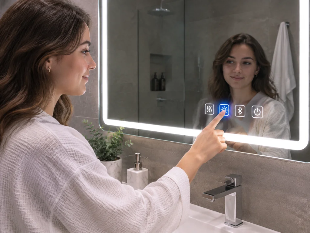
A smart mirror touch switch provides a clean, intuitive way to control lighting, demisting, Bluetooth audio, displays, and other integrated functions without adding a conventional mechanical button to the mirror surface. The right solution depends on the mirror construction, glass thickness, required sensing distance, electrical load, user environment, and the way the switch must interact with the mirror control system.
This guide explains how to evaluate a smart mirror touch control module, compare capacitive and non-capacitive approaches, plan installation, avoid common design errors, and select a touch switch for smart mirror applications that remains reliable in bathrooms, hotels, homes, and commercial interiors.
What a Smart Mirror Touch Switch Does
A smart mirror touch switch is an electronic interface that detects a user command through or near the mirror surface and sends a control signal to an attached circuit. In a typical installation, the user taps a marked area on the front of the glass. The sensor detects the change, and the control module switches a light, adjusts brightness, activates a defogging pad, or communicates with another smart mirror function.
The switch is usually made up of several functional elements: a sensing electrode, a controller, a power supply section, an output interface, and sometimes an indicator light or buzzer. These parts may be integrated onto one circuit board or supplied as a sensor and controller assembly. The physical button area can be identified with a printed icon, a translucent window, an engraved symbol, or an illuminated ring. This lets the mirror maintain a smooth appearance while preserving a clear user interface.
Unlike a mechanical push button, a touch interface has no exposed moving parts. That can improve appearance and reduce wear caused by repeated pressing. It also avoids a hole through the front glass in many designs. However, the absence of mechanical movement means that the electronics must be matched carefully to the glass, backing material, humidity, and installation distance. A component that works correctly on a thin dry sample may behave differently when installed behind a thicker mirror, a metal frame, a heating film, or a wall-mounted enclosure.
The most common commands include on and off control, short-touch activation, long-touch dimming, and multiple touch areas for separate functions. Some systems use one illuminated sensor for the main light and a second sensor for demisting. Others combine touch control with a remote control, mobile application, voice assistant, clock, display, or audio module.
- Primary benefit: a low-profile control surface that supports a clean mirror design.
- Typical functions: lighting, dimming, demisting, display activation, and auxiliary electrical control.
- Main engineering concern: stable sensing through the actual mirror assembly rather than through a bare test panel.
For this reason, the switch should be treated as part of the complete mirror system, not as an isolated accessory. The glass, coating, adhesive, enclosure, power source, and connected load all influence final performance.
Choosing Between Capacitive and Other Touch Technologies
A smart mirror capacitive touch switch is often selected because it can detect a finger through a non-metallic front surface. The sensor measures a change in an electric field when a user approaches or touches the designated area. This allows the visible control to remain behind glass, which is useful when the mirror must be easy to clean and visually uninterrupted.
Capacitive sensing is especially suitable for glass mirrors, acrylic panels, and other non-conductive front surfaces. Its performance is affected by electrode size, glass thickness, controller sensitivity, grounding, moisture, and nearby electrical noise. A thicker front layer generally reduces the signal available to the controller. Water droplets or condensation can also create unwanted changes in capacitance, so bathroom designs require appropriate sensitivity adjustment and physical separation from wet edges.
Other technologies may be appropriate in specific conditions. Infrared sensors can detect a hand without direct contact and can work through some front materials, but they require an optical path and may respond to unintended objects. Mechanical switches provide clear physical feedback and a simple electrical interface, but they need an opening, a moving part, or a visible protrusion. Proximity sensors can support gesture-style operation, although they may need more careful calibration in a crowded installation.
| Technology | Strengths | Limitations | Suitable use |
|---|---|---|---|
| Capacitive touch | Clean appearance, no moving parts, works behind glass | Sensitive to thickness, moisture, grounding, and electrical noise | Residential mirrors, hotel bathrooms, illuminated vanity mirrors |
| Mechanical switch | Simple circuit, clear tactile feedback, predictable actuation | Requires a physical opening or exposed component | Utility-focused products and accessible control panels |
| Infrared sensing | Contactless operation and useful hand detection | Needs optical alignment and may detect unintended movement | Hygienic commercial spaces and gesture-oriented designs |
| Proximity sensing | Can activate before direct contact and support touchless control | Requires careful range and environmental calibration | Premium mirrors and specialized installations |
Capacitive control is not automatically the best choice. If the mirror includes a conductive coating, a metal decorative layer, or a large heating element close to the sensor, another technology may provide more predictable results. The correct decision should follow a sample test using the finished stack-up, the intended power supply, and the actual wiring arrangement.
Key Specifications for a Smart Mirror Touch Control Module
When comparing a smart mirror touch control module, start with the electrical interface rather than the appearance of the sensor icon. The module must be compatible with the available input voltage, the connected load, and the control method required by the mirror. Common output arrangements include direct switching, relay output, low-voltage signal output, and communication with a separate lighting or appliance controller.
Input voltage is a critical specification. A module designed for a low-voltage DC system should not be connected directly to mains power unless the product documentation specifically supports that arrangement. In many mirror products, a certified power supply converts the incoming mains voltage to a low-voltage output for the touch electronics and LED lighting. Separating the sensing circuit from the high-voltage circuit can simplify product safety and reduce noise, but the complete assembly still needs appropriate insulation, enclosure protection, and installation procedures.
Load capacity must also be evaluated carefully. A lighting load may be resistive, capacitive, or inductive depending on the driver and lamp design. LED drivers can create inrush current or switching noise even when their normal operating wattage appears low. A touch switch that is suitable for a small LED strip may not be suitable for a motor, fan, heater, or high-power demisting element. If the load exceeds the module rating, an appropriately rated relay or external controller may be required.
Useful specifications to request from a supplier include sensing distance, recommended glass thickness, standby consumption, switching mode, operating temperature, humidity tolerance, output rating, and expected touch response. Also ask whether the sensor supports momentary operation, latching operation, dimming, or long-press control. These functions are not interchangeable. A module that toggles a light on and off may require a separate dimmer for brightness adjustment.
- Confirm the module input voltage and polarity before wiring.
- Match the output type to the LED driver or other connected equipment.
- Check the maximum permitted glass and adhesive thickness above the sensing electrode.
- Verify whether the module supports the desired short-touch and long-touch behavior.
- Request a wiring diagram and installation limits for bathroom or humid environments.
Specifications should be documented at the system level. The stated rating of a controller does not replace the safety requirements for the power supply, wiring, connectors, enclosure, and final mirror product. A professional supplier should be able to explain how the touch module is intended to operate inside the complete assembly.
Installation Through Glass and Mirror Construction
Installation quality has a direct effect on the reliability of a touch switch for smart mirror products. Before fixing the sensor, identify the complete layer structure: front glass, reflective coating, protective backing, adhesive, wall gap, sensor electrode, and any nearby conductive parts. The sensor should be positioned in the area where the user will naturally touch, while the rear of the electrode should remain separated from unintended metal surfaces.
The first practical step is to create a sample panel using the same glass type and approximate thickness as the production mirror. Mark the proposed touch area on the front surface and install the electrode in the intended rear position. Test the system with dry fingers, wet fingers, different lighting conditions, and the final power supply. If the mirror has a demister, LED driver, display, or audio circuit, test those components at the same time because their wiring can influence sensor stability.
Sensor alignment matters. A large offset between the visible icon and the electrode can make the switch feel inaccurate. Excessive adhesive between the electrode and the mirror can weaken detection, while air gaps can change the sensing behavior from one unit to another. The electrode should be fixed securely without creating bubbles, folds, or uneven pressure. If the design uses an illuminated indicator behind the glass, the LED should be centered with the marking and shielded from unwanted light leakage.
Metal frames, aluminum back panels, mounting brackets, and heating foils deserve special attention. They can alter the electric field or act as an antenna for interference. Keep conductive parts outside the sensing region where possible. When that is impossible, the controller may need a different electrode layout, shielding strategy, or sensitivity setting. Wiring should be routed consistently, with high-current or switching wires separated from the sensor lead.
Commissioning sequence
- Inspect the mirror for cracks, coating damage, trapped moisture, and loose sensor parts.
- Confirm the power supply output with a meter before connecting the controller.
- Test the sensor while the mirror is in its final mounted position.
- Operate every connected function repeatedly and observe false triggers or missed touches.
- Test after the mirror reaches normal bathroom humidity and temperature conditions.
A frequent installation mistake is calibrating the sensor on a workbench and assuming that the result will remain unchanged after wall mounting. The wall, frame, power cables, and adjacent appliances can all change the electrical environment. Final commissioning should therefore take place after the mirror has been installed in the location where it will be used.
Designing Reliable Controls for Bathroom and Commercial Use
Bathrooms create a more demanding environment than a dry indoor room. Condensation, splashing water, soap residue, steam, temperature changes, and wet hands can all affect the operation of a smart mirror touch switch. The visible control should be easy to locate and clean, but it should not create a point where water can enter the electronics. A sealed front surface is one advantage of touch control, provided the rear electronics are also protected.
Designers should distinguish between water resistance of the mirror and protection of the touch module. A mirror may have a sealed front but an exposed circuit board behind the backing. The controller, connector, and power supply need an enclosure or installation arrangement appropriate to the environment. The required protection level depends on the product design and installation zone, and it should be evaluated according to applicable electrical and bathroom safety requirements in the target market.
Control logic should be simple enough for repeated everyday use. A short tap can control the main light, while a long press can adjust brightness if dimming is supported. A second icon can operate the demister. In a hotel or rental property, clear symbols and consistent behavior are more valuable than a large number of hidden gestures. In a residential premium mirror, additional controls may be justified, but each function should have visible feedback.
Indicator lighting helps users understand status, especially when the mirror is used at night. The indicator should be bright enough to find without creating glare in the mirror reflection. Consider whether the light should remain on during standby, change color when a function is active, or turn off after a delay. These decisions affect standby consumption and the perceived quality of the product.
Commercial installations add further considerations. A hotel may require hundreds of mirrors with consistent sensitivity, replaceable modules, and documented wiring. Public washrooms may prioritize contactless operation and easy maintenance. Salons and dressing rooms may require accurate color lighting, frequent switching, and resistance to cleaning chemicals. The appropriate design is determined by the use pattern, not only by the mirror size.
Common errors include placing the sensor too close to the mirror edge, selecting a controller without humidity guidance, hiding all status feedback, and using a high-power appliance directly on a low-rated output. These issues can be reduced through sample testing, clear installation instructions, and a serviceable rear enclosure.
Performance Testing, Troubleshooting, and Maintenance
A structured test program helps determine whether a touch switch for smart mirror operation is ready for production. Begin with functional testing: confirm that each touch area performs the intended command, that the indicator matches the device state, and that the switch returns to the correct condition after power interruption. Repeat each command many times rather than relying on a single successful activation.
Next, test environmental and user variables. Try a light fingertip touch, a firm touch, a damp finger, and a touch through the normal cleaning surface. Check whether nearby hands or objects activate the sensor. Operate the mirror with the LED lighting at minimum and maximum brightness, with the demister active, and with any display or audio electronics running. This can reveal interference that is invisible during an isolated sensor test.
If the switch does not respond, first verify power, polarity, connector placement, and the distance between the electrode and glass. A protective film, thick adhesive layer, or unexpected backing material may be blocking the signal. If the sensor responds only intermittently, inspect grounding, cable routing, loose electrode attachment, and the stability of the power supply. If false activation occurs, look for moisture, a metal frame near the electrode, long parallel sensor wires, or electrical noise from an LED driver.
Calibration should be performed using a repeatable method. Record the mirror construction, sensor position, controller setting, and power supply model. Then apply the same test procedure to pilot units and production samples. This creates a reference for quality control and helps identify whether a problem is caused by component variation, assembly variation, or the installation environment.
- Missed touch: check glass thickness, sensor alignment, sensitivity, and electrode contact.
- False trigger: check condensation, metal proximity, cable routing, and unstable power.
- Unwanted reset: check voltage drop, driver inrush current, and overload conditions.
- Uneven indicator: check LED centering, diffuser placement, and printed marking alignment.
- Failure after cleaning: inspect sealing, chemical compatibility, and moisture paths behind the glass.
Maintenance is generally straightforward because there are no mechanical contacts on the visible surface. Clean the mirror according to the glass and coating manufacturer’s instructions, and prevent liquid from being directed toward rear openings or connectors. For commercial products, keep replacement specifications and wiring diagrams available so a failed controller can be identified without removing unrelated components.
How to Specify and Source the Right Smart Mirror Touch Switch
Successful sourcing begins with a complete technical brief. Instead of requesting only a “touch button for a mirror,” describe the mirror structure, control functions, electrical system, installation environment, and expected quantity. A supplier can then recommend a suitable smart mirror touch switch or identify where a standard module needs modification.
The brief should state the front material and thickness, sensor location, available power input, connected load, required output, indicator style, and desired user actions. Include drawings or photographs showing the frame, backing, demister, lighting zones, and available space. If the product will be sold in several countries, identify the target markets early because electrical, EMC, and safety documentation may differ.
Ask for samples that use the intended sensor, cable length, indicator, and controller. A sample with a different electrode or driver may not provide useful evidence. During evaluation, compare response consistency, touch effort, false activation rate, power consumption, heat generation, and behavior after repeated operation. Also review the module’s serviceability. A controller that can be replaced from the rear is more practical than one permanently trapped behind a sealed assembly.
Supplier communication should cover both performance and production control. Request information about incoming component inspection, firmware or sensitivity settings, end-of-line testing, and lot traceability. For larger projects, define acceptance criteria such as successful activation percentage, maximum false-trigger rate during a specified test period, and allowable indicator variation. These criteria make quality discussions objective.
| Specification area | Information to provide | Why it matters |
|---|---|---|
| Mirror construction | Glass type, thickness, coating, backing, adhesive, and frame | Determines sensing strength and interference risk |
| Electrical system | Input voltage, driver type, load wattage, and wiring length | Prevents overload, resets, and incompatible switching |
| User interaction | Tap, long press, dimming, separate zones, and indicators | Ensures the controller behavior matches the product experience |
| Environment | Bathroom, hotel, retail, salon, temperature, and humidity | Guides protection, sealing, and validation requirements |
| Compliance | Target markets and required technical documentation | Supports legal sale and responsible installation |
The best product is not necessarily the least expensive module. A reliable touch interface reduces customer complaints, replacement labor, and warranty exposure. Evaluate total cost across the controller, wiring, assembly time, testing, service access, and expected product life. With a clear specification and a finished-mirror validation sample, buyers can select a touch switch for smart mirror products that is attractive, dependable, and practical to manufacture.
For a project requiring a smart mirror touch switch, prepare the complete mirror stack-up, electrical load information, target application, and expected operating environment before requesting a quotation. Contact a qualified supplier for a sample evaluation and technical review, then approve the module only after testing it in the finished mirror assembly.
You might also be interested in
Learn how to select, install, test, and source a smart mirror touch switch for reliable lighting, demisting, and control in residential and commercial applications.

The Complete Guide to Mirror Touch Switch Modules: Technology, Manufacturing, and Customization
Explore the technology, manufacturing quality, supplier logistics, and customization of mirror touch switch modules, including specs, installation tips, and smart home trends.

Bathroom Mirror Touch Switch: How to Choose, Specify, and Source the Right Solution
A bathroom mirror touch switch improves modern mirror design with clean operation, reliable control, and OEM flexibility. This guide explains selection, sourcing, and testing.

The Complete Guide to Mirror Switch Modules: Technology, Selection, and Installation
A mirror switch module controls lighting, dimming, and defogging in smart bathroom mirrors. This guide covers capacitive, infrared, and mechanical types, key electrical specifications, installation steps, selection criteria, and quality-testing practices for reliable LED mirror applications.